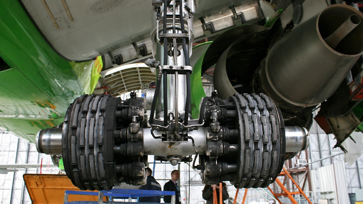
Aircraft brakes stop a moving aircraft by converting its kinetic energy to heat energy by means of friction between rotating and stationary discs located in brake assemblies in the wheels.
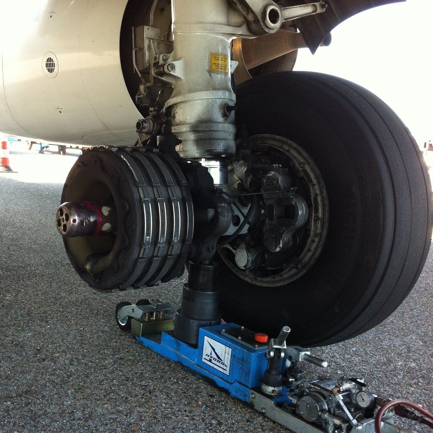 A brake assembly on a Boeing 737NG main landing gear, visible after removal of one the wheels. Source: SKYbrary (Click image to enlarge)
Brakes provide this critical stopping function during landings to enable airplanes to stop within the length of the runway. They also stop aircraft during rejected takeoff events, in which an attempted takeoff is canceled as the airplane is rolling down the runway before it lifts off from the ground due to engine failure, tire blowout, other system failure or direction from air traffic control.
Aircraft brakes also prevent motion of the aircraft when it is parked, limit its speed during taxiing and can even help steer the aircraft on the ground by applying different levels of braking force to the left- and right-side brakes.
Aircraft brakes work in conjunction with other brake mechanisms such as thrust reversers, air brakes and spoilers. Thrust reversers are surfaces that are deployed into the path of the jet blast from the engines to redirect propulsive thrust in a direction that opposes the motion of the aircraft. Air brakes and spoilers are flight control surfaces that create additional aerodynamic drag when deployed into the path of air flowing around the aircraft.
How aircraft brakes work
The most common type of brake used on aircraft is the disc brake. Disc brakes function by exploiting friction between rotating and stationary discs inside the brake.
Upon receiving a command signal to brake — from the pilot depressing a foot pedal or from the autobrake system — actuators in the brake move a piston to squeeze the discs together, generating a frictional force that slows the rotation of the wheel. The friction between the discs generates heat as the aircraft’s kinetic energy is converted to heat energy. In this function, the brakes act as a heat sink, absorbing tremendous amounts of heat as the aircraft sheds kinetic energy. During RTO stops, the temperature of carbon disc brakes can exceed 1,800° C.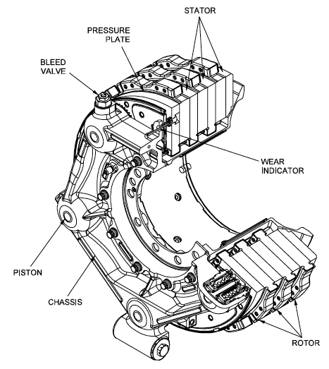 Gulfstream G450 main landing gear brake assembly. Source: G450 Maintenance Manual via Code 7700
The discs are mounted on a carrier assembly consisting of a torque tube, which resists and transmits brake torque to the landing gear structure. Sandwiched together between the carrier assembly housing and a backing plate, the discs are arranged in an alternating pattern of rotors and stators. Notch and groove geometry around the circumference of each rotor fits into corresponding geometry in the wheel, keying the rotors to the wheel so that they rotate with it. The stators are keyed to the torque tube and are thus held stationary since the torque tube is connected to the axle and landing gear structure.
Cylindrical spaces within the carrier assembly hold actuator pistons. Braking occurs as piston force squeezes the discs together.
During each application of the brakes, disc material is worn away by frictional forces. A wear indicator in the form of a pin that protrudes out of the carrier assembly indicates the thickness of the stack of discs. Over hundreds of brake applications, material wears away and discs become thinner, requiring replacement following periodic maintenance intervals.
Brake design
The primary design considerations for aircraft brakes include the number of discs, the diameter of the discs and the material of the discs.
A major design point around which aircraft brakes are designed is the worst-case scenario of rejected takeoff (RTO) at the maximum rolling speed V1, known as the decision speed. Above V1, a takeoff could not be safely aborted without serious risk of the airplane failing to stop before the end of the runway. In this situation, the brakes need to absorb more energy than any other scenario.
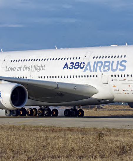 An A380’s brakes exhibit a red-hot glow during a rejected take off (RTO) test on the runway at ISTRES AFB in the south of France. Source: Airbus (Click image to enlarge)
To illustrate how much energy this is, consider an Airbus A380 — the world’s biggest passenger airplane — performing an RTO at V1. The maximum take-off weight of an A380 is 575,000 kg (1,267,658 lb) and its maximum V1 is around 170 knots (about 195 mph or 87 m/s). A rough estimate for the maximum energy that the A380’s 16 brakes need to dissipate during RTO can be obtained by calculating the kinetic energy of the aircraft (neglecting the effects of thrust reversers, air brakes, tailwinds, headwinds and runway slope).
Since kinetic energy (KE) is a function of mass (m) and velocity (v) according to the equation:
KE = ½mv2
The kinetic energy of the A380 during RTO is calculated as follows:
KE = 0.5 * 575,000 kg * (87.4556 m/s)2 = 2.2 x 10⁹ J = 2.2 GJ
2.2 GJ (gigajoules) is about the amount of energy an average cloud-to-ground lightning strike dissipates. It is also enough energy to power an 8 W LED light bulb (with light output equivalent to a 60 W light bulb) continuously for 8 years and 10 months.
To generate the necessary frictional forces and to handle this much energy within the length of a runway, large commercial transport aircraft typically require multiple discs per brake assembly and brakes on most, if not all, of their wheels.
For example, an A380 has 22 wheels distributed on five landing gear legs to support its massive weight: two nose wheels on a leg beneath the nose of the aircraft, eight wing wheels split between two legs that fold out from under the fuselage to support the left and right wings, and 12 body wheels split between two inboard landing gear legs under the fuselage. Sixteen of these wheels have brakes (four aft body wheels and the nose wheels are not braked).
The A380 uses Honeywell’s Carbenix brakes. Each of the aircraft’s 16 brake assemblies has five rotors made of Carbenix 4000 carbon-carbon composite. The brake assemblies are located within wheels made of 2014-T6 aluminum alloy and attached to the axle and landing gear structure, which is comprised of 300 M high-strength alloy steel, titanium and aluminum components.
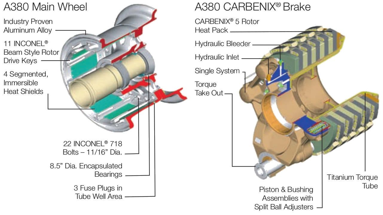 A380 main wheel and brake. Source: Honeywell (Click image to enlarge)
Brake materials
The most common aircraft brake disc material until around 1963 was steel. The introduction of beryllium as a disc material provided improved thermal properties at the cost of material handling difficulties due to the toxic nature of beryllium oxide.
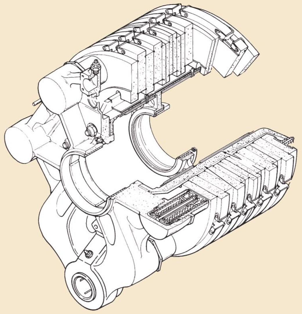 Boeing 767 carbon brake. Source: Honeywell Landing Systems via Boeing (Click image to enlarge)
Carbon brakes became widely available for commercial airplanes starting in the 1980s. Carbon brakes — made of, for example, carbon fibers in a graphite matrix — are lighter, more durable, less thermally sensitive and have higher energy absorption and faster cooling rates compared to steel brakes.
Compared to steel, carbon’s higher specific heat — the amount of heat that a unit mass of carbon absorbs to raise its temperature by one unit — enables reduced brake weight. Carbon’s higher thermal conductivity allows faster heat transfer and uniform heat distribution through the disc. Carbon also has lower thermal expansion, higher thermal shock resistance and a higher temperature limit than steel. The specific strength of carbon is relatively constant over a very wide range of temperatures, unlike steel and beryllium, which both exhibit steep declines in specific strength at high temperatures, dropping below carbon around 650° C (1,200° F).
Safran Landing Systems claims its Sepcarb III oxidation-resistant carbon brakes used on Boeing 787s are four times lighter, have three times higher endurance and have two to three times higher absorption capacity than steel brakes. UTC A

